Electronics & Communication Engineering

Experiential learning creates a deeper understanding of course content, promotes critical thinking and problem-solving, and allows students to actively participate, reflect, and apply new knowledge and skills. The goal of electronics and communication engineering Experiential Learning (EL) activities encompass lifelong learning, design process, and embodying interdisciplinary interventions for solving open ended problems. Experiential learning activities provide opportunities for students to explore the synergies between different disciplines like design of analog and digital circuits, power supply, RF and HDL circuits through hands-on projects and practical applications.


EL Coordinators:Dr. Anil Arora and Dr. Sandeep Mandia


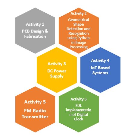
Semester 1: PCB Design &Fabrication


A PCB is a printed circuit board, also known as a printed wiring board. It is used in electronics to build electronic devices. A PCB serves two purposes in the construction of an electronic device; it is a place to mount the components and it provides the means of electrical connection between the components. Printed circuit board (PCB) design brings your electronic circuits to life in the physical form. Using PCB layout software, the PCB board design process combines component placement and routing to define electrical connectivity on a manufactured circuit board. On the other hand PCB fabrication is the process or procedure that transforms a circuit board design into a physical structure based upon the specifications provided in the design package.

Faculty Facilitator

Dr. Anil Arora
Dr Arnab Pattanayak

The basic outline of the activity is:

  • Introduction to PCB Design: Start by introducing students to the concept of PCBs, their importance in electronics, and the basics of PCB design.
  • Software Familiarization:Provide tutorials or demonstrations on how to use the software to create schematics, layout designs, and generate manufacturing files.
  • Project Selection: Allow students to select simple projects like an LED flasher, a basic Arduino project etc.
  • PCB Layout Design: Once the schematic is complete, instruct students on how to translate it into a PCB layout. Teach them about component placement, routing traces, optimizing signal integrity, and minimizing noise.
  • Assembly and Testing: Once the PCBs are fabricated, guide students through the assembly process. Teach them how to solder components onto the board correctly.
  • Quality Control and Troubleshooting: To perform quality control checks on their finished PCBs, such as continuity testing, voltage measurements, and signal integrity analysis.
  • Reflection and Documentation: Encourage students to reflect on their learning experience and document their process, challenges faced, and lessons learned.


Semester 2: Geometrical Shape Detection and Recognition using Python in Image Processing


‘Geometrical Shape Detection and Recognition using Python in Image Processing’ is a hands-on activity where students learn to utilize Python programming and image processing techniques to detect and recognize geometric shapes in digital images. The activity begins with an introductory session covering fundamental concepts of image processing, including image representation, pixel manipulation, and basic filtering techniques. Students then transition into hands-on exercises, where they explore the OpenCV library and NumPy to implement algorithms for edge detection and contour extraction.

Faculty Facilitator

Dr. Geetika Dua
Dr. Dinesh
Dr. Shashikant
Dr. Ram Kishan Dewangan Dr. Ashu Sharma

The basic outline of the activity is:

  • Introduction to Image Processing and Computer Vision: Explain how computers interpret and analyze digital images to extract information.
  • Python and OpenCV Setup: Guide students through setting up Python and installing OpenCV, a popular library for computer vision tasks.
  • Image Loading and Preprocessing: Load an image using OpenCV and preprocess it for shape detection tasks. This may include resizing, converting to grayscale, and applying any necessary filters for noise reduction.
  • Coding Session: Conduct a hands-on coding session where students implement shape detection algorithms in Python using OpenCV. Provide sample images containing geometrical shapes for them to work with.
  • Shape Recognition and Classification: Once students are familiar with shape detection, introduce the concept of shape recognition. Ask them to classify detected shapes based on their properties such as number of sides, angles, and area.
  • Evaluation and Testing: Encourage students to evaluate their shape detection and recognition algorithms using test images. Measure metrics such as accuracy, precision, and recall to assess the performance of their models.


Semester 3: DC Power Supply


Power supply is a common reference to the source of electrical power. Most electronic circuits require a DC power supply. The main purpose of DC power supplies is to produce a regulated voltage output for electronic and electric devices. Unlike AC voltage, DC voltage cannot be stepped up or stepped down using a transformer.

Faculty Facilitators

Dr.Neeru Jindal
Dr.Shishir Maheshwari
Dr.Sumit Vyas
Dr.Sujit Patel

The basic outline of the activity is:

  • Differentiate between AC and DC power, and discuss why regulated DC power is essential for electronic devices.
  • Students will learn about the components typically found in a DC power supply, including transformers, rectifiers, filters, voltage regulators, and output protection circuits. Explain the function of each component and how they work together to produce a stable DC output.
  • Hands-On Construction: Provide students with kits containing components to build a simple linear regulated DC power supply circuit.
  • Circuit Analysis and Troubleshooting: Students will measure voltages and currents at various points in the circuit using multimeters. Encourage them to troubleshoot common problems such as short circuits, open circuits, and voltage drops.
  • Understand the concept of voltage regulation and demonstrate how the voltage regulator component in the circuit maintains a constant output voltage despite changes in input voltage or load conditions. Discuss the importance of stability and accuracy in voltage regulation.


Semester 4: IoT Based Systems


The Internet of things (IoT) is the networks use to interface the physical objects. These are the system of interrelated, internet-connected objects those are able to collect and transfer data over a wireless network without human intervention. The different sensors, actuator, software, and other technologies are embedded for the purpose of connecting and exchanging data with other devices and systems over the Internet. This ELC activity focuses on hands-on IoT concepts such as sensing, actuation and communication. It will focus on the development of Internet of Things (IoT) based prototypes including devices for sensing, actuation, processing, and communication which will help the students to develop skills and experiences.

Faculty Facilitator

Dr. Karmjit Singh Sandha Dr. Hem Dutt Joshi

The basic outline of the activity is:

  • Interface the various sensors and actuators and their programming with embedded systems.
  • Control the working and functioning of interfaced sensors and actuators through IoT.
  • Exposure to monitor and control the operation of IoT based appliances at home, office and industry.


Semester 5: FM Radio Transmitter


This activity is related to design and development of FM radio transmitter in which students learn about the various stages of FM radio Transmitter, need of the frequency tuning of FM radio, need of matching circuit for transmitter, exposure to equipment’s used for testing of a radio transmitter, and sSafety features in an industrial equipment. With the help of given components, students design transmitter on PCB board and the final testing of frequency of transmission has been done on hand held spectrum analyzer.

Faculty Facilitator

Dr. Surbhi Sharma
Dr Rajesh Khanna

The basic outline of the activity is:

  • Introduction to FM Radio Transmitters: Understand the concept of FM (Frequency Modulation) radio transmitters, its working, their importance in broadcasting, and their applications in communication systems.
  • RF Circuit Components: Learn about the components typically found in an FM radio transmitter circuit, including oscillators, modulators, amplifiers, and antennas. Explain the function of each component and how they contribute to the overall operation of the transmitter.
  • Frequency Modulation: Understand the concept of frequency modulation and how it differs from amplitude modulation (AM). Know the advantages of FM, such as higher audio fidelity and better resistance to noise.
  • Hands-On Construction: Provide students with kits containing components to build a simple FM radio transmitter circuit. Alternatively, set up workstations with breadboards or PCBs where students can assemble the circuits themselves.
  • Transmitter Range Testing: Set up a receiving station equipped with an FM radio receiver and antenna. Have students test the range of their transmitters by transmitting signals and observing how far they can be received without significant degradation in quality.


Semester 6: HDL implementation of Digital Clock


Hardware Description Languages (HDLs) are extremely important tools for modern digital designers. Once a student has learned HDL such as VHDL or Verilog, he/she will be able to design complex digital systems with ease and in quicker way. Debugging is also much faster because it requires only the code change. Aim of this ELC activity to design and implement a digital clock (with hours, minutes and seconds) using HDL. Xilinx Vivado WebPack will be used to simulate and synthesis the HDL code. After synthesis, they will be able to see the actual hardware required in digital clock.

Faculty Facilitator

Dr. Manu Bansal
Dr Anil Singh

The basic outline of the activity is:

  • Introduction to HDLs: Explain how HDLs are used to describe the behavior and structure of digital circuits at various levels of abstraction.
  • Introduction to Verilog or VHDL: Introduce students to Verilog or VHDL, the two most commonly used HDLs in the industry. Explain the syntax, structure, and semantics of the language, as well as the differences between Verilog and VHDL.
  • Hands-On Coding Session: Conduct a hands-on coding session where students write simple Verilog or VHDL code to implement basic digital logic circuits such as adders, multiplexers, and flip-flops. Provide sample code and exercises to help students practice writing HDL code.
  • Introduce students to HDL simulators such as ModelSim or Xilinx Vivado Simulator. Show them how to simulate their Verilog or VHDL code to verify its functionality and debug any errors or issues.
  • FPGA Implementation: Provide students with access to FPGA development boards or simulators such as Xilinx Vivado or Altera Quartus. Guide them through the process of synthesizing and implementing their Verilog or VHDL code on an FPGA